
Wednesday, April 29, 2015

THE HYDROBEE: USB POWER FROM NATURE

We just received an email from a company called Hydrobee, asking us to vote for themas Autodesk’s inventor of the Year. Having never heard of this we checked it out… what a neat invention! This soda-can sized device generates electricity for USB devices when you’re off the grid. It can generate power using flowing water, a hand crank, small wind turbine,solar power, pedal power, kinetic energy and more.
The hydrobee doesn’t directly charge devices, instead it charges six internal AA batteries which can then be used to charge your devices. Genius. Hopefully this company gets the funding they need to start producing soon, as this could be very helpful to people in remote and impoverished areas. They’ve definitely got our vote!
Watch the video:
Photos:


What do you think of this invention?


How Does a Heat Pump Work?
Everything you need to Know about its operation?
The
Heat Pump is very simple once you understand the basic concept (and I
promise you will after reading this). As the name suggests a heat-pump
transfers or pumps heat from one place to another, (notice the use of the word “pump”- heat is not generated but rather is moved).
As they say “a picture worth a thousand words”. So let’s see one:

In this Example:
- The flame heats up the water.
- The hot water is pumped to the radiator.
- The fan forces the Cold Air over the Hot Radiator and the air becomes hot.
- The water becomes cold because the heat has been transferred from the water to the air. The cold water is then pumped back to water tank- where it is heated up again (Step 1).
- Notice in this example that the flame generates the heat. We transfer that heat to the air using a medium (in this case the water) pumped through a radiator. Pumped heat- a heat pump!
- The real heatpump doesn't differ that much from this simple example- we just replace the water with a refrigerant (such as Freon) and replace the water pump with a compressor.
The real Heat Pump in action
Cooling Mode (regular Air Conditioning)
Cooling Mode (regular Air Conditioning)
Hold on a minute- Does that mean a regular air conditioner is considered to be a heat pump?
Well let’s see:
- Heat is generated inside your house- from sun shining through windows and onto the roof and walls, from appliances and from your body. This is the equivalent of the flame heating the water in our first example.
- Your air conditioner transfers that heat from inside your house to outside your house. This is the equivalent of the pump and radiator
So
in theory- yes, any regular air conditioner can be considered to be a
heat pump (but don’t tell this to your repair man or you will confuse
him!)
So what is different between your regular air conditioner and a heat pump?
Before we discuss the difference let’s see how the heat pump acts in Cooling Mode:

Before we start notice three things:
- The position of the Reversing Valve
- The Direction of the flow of the refrigerant.
- The inlet and outlet ports of the Compressor (those will never change) Did you notice?
OK- Let’s continue and we’ll start at Point 1 on the diagram
- Point 1 At the beginning of the cycle the refrigerant (such as Freon) is in a liquid form (gas contained under pressure becomes a liquid just like the propane in the tank that you use to BBQ that juicy steak). This liquid refrigerant is very cold. It enters the evaporator coil located inside your house. The hot air in your house moves over the coil and the air starts to lose its heat and cool down.
- Point 2 After the refrigerant leaves the indoor evaporator coil it has absorbed heat and become gas. Just like when you heat water on the stove and it becomes steam the refrigerant gas evaporated when it absorbed all that heat in the house (that’s why we call this coil the evaporator) The refrigerant enters the compressor which mechanically pressurizes the gas. That process will increase its temperature so the refrigerant will leave the compressor as hot gas.
- Point 3 The refrigerant next moves to the condenser coil located outside the house. Because the temperature outside is lower than the temperature of the hot gas the heat is transferred or “rejected” from the refrigerant in the coil to the outside air. As the temperature of the refrigerant gas cools it will form liquid condensate- just like the water droplets that form on a cold glass of soda (that’s why we call this coil the condenser).
- Point 4 The refrigerant leaves the outdoor condenser coil as warm liquid. Now we need to make the warm liquid refrigerant cold so that it can absorb more heat. So it goes to the metering device which drops the pressure on the warm liquid and thus drops its temperature. The refrigerant leaves the metering device as a cold liquid, ready to repeat the cycle again.
Well that wasn't too bad was it? Did you understand it or you need to go over it one more time?
For
a fun (and safe!) experiment, put your hand to feel the air that is
blowing out of your Condenser Unit (that big ugly box sitting in your
back yard or over the roof). In the summer time you will feel hot air
is coming out- that is the heat from inside the house! If you don’t
feel hot air coming out, that means either your Compressor is not
working or you are out of refrigerant and your air conditioner needs to
be recharged with more refrigerant.
Now what about heating- how does that work?
Well let’s look at the next diagram:
Did you notice what just happens?
Here are the two diagrams, side by side. Look carefully this time:

Look at the reversing valve
it Rotates 90o , that changes the direction of the flow of the
refrigerant (Freon). It goes in the opposite direction and this is the
reverse of the cooling cycle. Instead of absorbing heat from inside the
house it absorbs heat from the air outside the house and “rejects” (or
transfers) that heat to the indoor air. Now the indoor coil has become
Condenser and the outdoor coil has become Evaporator
Notice
that the heat isn’t generated by an oil burner or a gas furnace. It is
just moved (or pumped) from the outside air to inside the house. This is
why the Heat Pump is so popular in moderate climates. You don’t need to
have a furnace or get oil or gas delivered when the weather cools
off.Because of the reversing valve you can use the same electric system
as both an air conditioner and a heater!
For
a fun (and safe!) experiment, try this. Take a regular window unit that
you buy at any department store. Install it facing the other direction
so the control panel is facing outside. Even though it is an air
conditioner you will get hot air in your house. The air conditioner is
actually a heater when it is reversed- this is the function and effect
of the reversing valve. It changes the direction of the refrigerant and
can make an air conditioner a heater or a heat Pump
Let’s summarize things up:
· Heatpumps (or air conditioners) don’t generate heat. The heat already exists inside your home.
· It is exactly like an air conditioner- it moves the heat from one place to anther.
· The only different is that in heatpumps we have a Reversing Valve
that allows us to chose to move the heat from inside the house to the
outdoors (cooling mode) or to reverse the cycle and remove the heat from
outside the house to the indoors (heating mode).
· Air
conditioners don’t have a Reversing Valve so they can only move the
heat from inside the house to the outdoors (cooling mode only).
·One more thing the heat pump thermostat is completely different than a regular air conditioner thermostat. So make sure that you are using
the right one (we will cover that topic later).
the right one (we will cover that topic later).
Didn’t I promise you will understand it?
There are so many types of heat pumps which we will discuss throughout this website. For example, we will examine Air To Air, Geothermal, Water Heater, Swimming pool, and Hybrid (Dual Fuel) HeatPumps.
American Wire Gauge (AWG) Cable / Conductor Sizes and Properties . |
||||||||||||||||||||||||||||||||||||||||||||||||||||||||||||||||||||||||||||||||||||||||||||||||||||||||||||||||||||||||||||||||||||||||||||||||||||||||||||||||||||||||||||||||||||||||||||||||||||||||||||||||||||||||||||||||||||||||||||||||||||||||||||||||||||||||||||||||||||||||||||||||||||||||||||||||||||||||||||||||||||||||||||||||||||||||||||||||||||||||||||||||||
|
|
| |||||||||||||||||||||||||||||||||||||||||||||||||||||||||||||||||||||||||||||||||||||||||||||||||||||||||||||||||||||||||||||||||||||||||||||||||||||||||||||||||||||||||||||||||||||||||||||||||||||||||||||||||||||||||||||||||||||||||||||||||||||||||||||||||||||||||||||||||||||||||||||||||||||||||||||||||||||||||||||||||||||||||||||||||||||||||||||||||||||||||||||||||

Tuesday, April 28, 2015


Common electrical units used in formulas and equations are:
- Volt - unit of electrical potential or motive force - potential is required to send one ampere of current through one ohm of resistance
- Ohm - unit of resistance - one ohm is the resistance offered to the passage of one ampere when impelled by one volt
- Ampere - units of current - one ampere is the current which one volt can send through a resistance of one ohm
- Watt - unit of electrical energy or power - one watt is the product of one ampere and one volt - one ampere of current flowing under the force of one volt gives one watt of energy
- Volt Ampere - product of volts and amperes as shown by a voltmeter and ammeter - in direct current systems the volt ampere is the same as watts or the energy delivered - in alternating current systems - the volts and amperes may or may not be 100% synchronous - when synchronous the volt amperes equals the watts on a wattmeter - when not synchronous volt amperes exceed watts - reactive power
- Kilovolt Ampere - one kilovolt ampere - KVA - is equal to 1,000 volt amperes
- Power Factor - ratio of watts to volt amperes
Electric Power Formulas
P = V I (1a)P = R I2 (1b)P = V2/ R (1c)whereP = power (watts, W)V = voltage (volts, V)I = current (amperes, A)R = resistance (ohms, Ω)
Electric Current Formulas
I = V / R (2a)I = P / V (2b)I = (P / R)1/2 (2c)
Electric Resistance Formulas
R = V / I (3a)R = V2/ P (3b)R = P / I2 (3c)
Electrical Potential Formulas - Ohms Law
Ohms law can be expressed as:
V = R I (4a)V = P / I (4b)V = (P R)1/2 (4c)
Example - Ohm's law
A 12 volt battery supplies power to a resistance of 18 ohms.
I = (12 V) / (18 Ω)= 0.67 (A)

Electrical Motor Formulas
Electrical Motor Efficiency
μ = 746 Php / Pinput_w (5)whereμ = efficiencyPhp = output horsepower (hp)Pinput_w = input electrical power (watts)
or alternatively
μ = 746 Php / (1.732 V I PF) (5b)
Electrical Motor - Power
P3-phase = (V I PF 1.732) / 1,000 (6)whereP3-phase = electrical power 3-phase motor (kW)
Electrical Motor - Amps
I3-phase = (746 Php) / (1.732 V μ PF) (7)whereI3-phase = electrical current 3-phase motor (amps)
How does Electrical Power work?
If you’re not electrically minded, think of electrical power as something easier to visualize like mechanical power. Mechanical and electrical power are very different, but both deliver power using pressure and flow, and the power delivered can be calculated by multiplying the pressure times the flow. In mechanical power, many terms are used to describe the pressure (Pounds per Square Inch, etc.) and flow (Gallons per Minute, etc.). In electric power, one term is used to describe the pressure (Voltage) and two terms are used to describe the flow (Amperes, Current).
In the earliest days, electrical power was delivered using Direct Current (DC), meaning the power flows in one direction like a water hose. Now, electrical power is delivered using Alternating Current (AC), meaning the power flow is constantly alternating directions. This change took place because electrical power can be delivered more efficiently using Alternating Current (AC) than Direct Current (DC). In the US, 60 Hertz (cycles per second) is the Alternating Current (AC) frequency. In some countries, 50 Hertz (cycles per second) is the Alternating Current (AC) frequency.
What does 1 (Single) Phase Power mean?
If you’re not electrically minded, think of 1 (Single) phase power like a one pedal bicycle where one (pushing leg) provides power.
Single Phase power refers to a two wire Alternating Current (AC) power circuit. Typically there is one power wire and one neutral wire. In the US, 120V is the standard single phase voltage with one 120V power wire and one neutral wire. In some countries, 230V is the standard single phase voltage with one 230V power wire and one neutral wire. Power flows between the power wire (through the load) and the neutral wire.
What does 2 (Dual / Split) Phase Power mean?
If you’re not electrically minded, think of 2 (Dual / Split) phase power like a two pedal bicycle where one (pushing leg) or both (pushing legs) can provide power.
Dual Phase or Split Phase power is also Single Phase because it’s a two wire Alternating Current (AC ) power circuit. In the US, this is the standard household power arrangement with two (Phase A, Phase B) 120V power wires (180 degrees out of phase with one another) like two bicycle pedals and one neutral wire. This arrangement provides (2) 120V and (1) 240V power circuits. 120V power flows (alternating) between either power wire (through the load) and the neutral wire. 240V power flows (alternating) between the two power wires (through the load).
This arrangement is used in most US households because of its flexibility. Low power loads (lights, TV, etc.) are powered using either 120V power circuit and high power loads (Water Heaters, AC Compressors) are powered using the 240V power circuit.
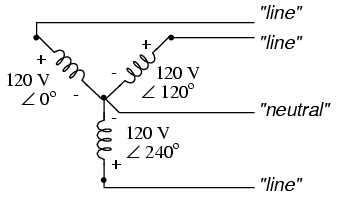
What does 3 (Three) Phase Power mean?
If you’re not electrically minded, think of 3 (Three) phase power like a three cylinder engine where three (pushing pistons) provide power.
Three Phase power refers to three wire Alternating Current (AC) power circuits. Typically there are three (Phase A, Phase B, Phase C) power wires (120 degrees out of phase with one another) and one neutral wire. For our purposes let’s consider a 3 Phase 4 Wire 208Y/120V power circuit. This arrangement provides (3) 120V single phase power circuits and (1) 208V three phase power circuit. 120V power flows (alternating) between any power wire (through the load) and the neutral wire. 208V power flows (alternating) between the three power wires (through the load).
Most US commercial buildings use a 3 Phase 4 Wire 208Y/120V power arrangement because of its flexibility. Low power loads (lights, computers, etc.) are powered using any 120V single phase power circuit and high power loads (Water Heaters, AC Compressors) are powered using the 208V three phase power circuit.
Most US industrial facilities use a 3 Phase 4 Wire 480Y/277V power arrangement because of its power density. Compared to single phase power circuits, three phase power circuits provide 1.732 (the square root of 3) times more power with the same current.
Using a 3 Phase power arrangement saves on electrical construction costs by reducing the current requirements, the required wire size, and the size of associated electrical devices. It also reduces energy costs because the lower current reduces the amount of electrical energy lost to resistance (converted to heat).
Subscribe to:
Comments (Atom)